

The following sections describe known software bugs, and applicable solutions/workarounds, for the different versions of ORBIS. If you have found a bug not included here, please contact us to report it.
Problem: External load component Fyy does not follow right-hand coordinates.
Cause: Fyy load component was flipped.
Solution: This bug is fixed in V5.1. For prior versions, flipping the sign of Fyy will also work. Note this issue is restricted to the Flexible Shaft results only.
Problem: Sketch figure, in the results, was not persistent and could be changed by altering the setup in the main interface.
Cause: Sketch image was referenced by pointer.
Solution: This bug is fixed in V5.0.
Problem: Film parameter lambda was misspelled in various locations in the results output and sensitivity data export headers.
Cause: Label typo.
Solution: This bug is fixed in V5.0.
Problem: System setups consisting of 5 bearing rows will not run.
Cause: An array index error caused code to abort.
Solution: This bug is fixed in V4.2. Unfortunately, there is no work around for this issue in V4.1.
Problem: 4PT bearing database editor does not allow the user to edit or remove 4PT bearings from their database.
Cause: Invalid pointer in database management code caused faulty logic.
Solution: This bug is fixed in V4.2. For V4.1 users the work-around is to add a new 4PT bearing to the database instead of editing an existing bearing. Note that there is no way to remove 4PT bearings from the database in V4.1.
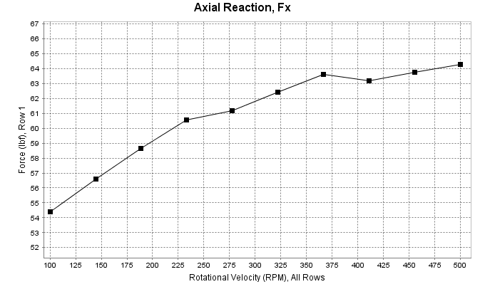
Problem: As bearing speed increases, the lubricant film thickness develops (increases). This film development causes certain system configurations to have increased preload. However, film thickness is a function of the normal ball load at the contact. This problem is circular and requires a interative solver loop to converge on both operational preload and developed film thickness. V4.1 did not complete the iterative solver loop, which resulted in small errors in the results for film thickness and operational preload.
Cause: Code logic only allowed one iteration to occur.
Solution: This bug is fixed in V4.2. In many cases the resulting error from this bug will be small. Image below shows reaction force on one row of a hard mounted duplex pair versus speed. As shown, the profile of the curve is non-smooth due to small errors in each solution point.
Problem: There were a number of typos in the results output. All typos were associated with descriptive text and not numeric results. For instance, on 4PT bearing output the data headers for the various possible contacts should be labeled as Inner Left, Inner Right, Outer Right and Outer Left. However, a few of these were mis-labeled.
Cause: Copy/paste errors and/or typos.
Solution: This bug is fixed in V4.2. In most cases the typo should be obvious. However, if there is doubt what the label means please contact us for clarification.
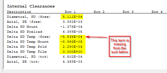
Problem: Result output, titled "Diametral,PD (tot)", reports incorrect value for bearings with non-ambient temperature loading.
Cause: Term, titled "Delta PD Temp (free)", is missing from the summation (see image below). Issue restricted to this specific output only.
Solution: The correct total clearance can be manually computed by summing the terms highlighted in yellow (see image below).
Problem: When using the Batch Process Load Cases tool and selecting the checkbox to save individual result files, the saved files start at index zero instead of one (i.e. the first file might be loadcase-0.txt instead of loadcase-1.txt).
Cause: Incorrect indexing logic in code.
Solution: There is no work-around, unless the user wants to rename the files. However, the saved files are complete and sequential based on user defined load cases. Mapping to load cases will be load # minus 1.
Problem: Orientation of Fz component does not follow right hand rule (it is flipped 180 degrees).
Cause: Incorrect sign in code. This issue is restricted to the Fz load direction, which can influence the sign of any associated R-Cross-F moments. However, system equilibrium is still valid.
Solution: This bug is fixed in V4.0. If still using V3.1, reverse the sign on the Fz load component to preserve the intent of a right-handed sense for this load component.
Problem: Thermal loads with axial gradients will not evaluate properly if the rows are not defined in sequential order from left to right.
Cause: Thermal expansion logic assumes rows are placed sequentially from left to right. This issue can influence the preload at temperature, thereby impacting multiple result output.
Solution: This bug is fixed in V4.0. If using V3.1, define system such that subsequent row positions have increasing x-axis locations.
Problem: Result output, titled "Axial stiffness with ring compliance", is incorrect.
Cause: Logic does not properly account for mounted preload when computing two point slope. Issue restricted to this specific output only.
Solution: This bug is fixed in V4.0. If using V3.1, correct stiffness can be computed as follows. Setup bearing system without external loading and run two cases with preload values below and above desired preload (perhaps use 99# and 101# for a nominal 100# preload). Axial stiffness can then be computed by summing the ratio of the change in final preload divided by change in axial inner ring displacement (dx) for each bearing row in the system.
Problem: Plot for total torque, in the Sensitivity Studies tool, will produce erroneous results if the row-wise bearing torques are not all equal.
Cause: Torque summation logic calculates total torque by getting the torque from the selected output row and multiplying by the number of rows in the system. It should be summing the torque from each row. This issue is restricted to the Sensitivity Studies plot results only.
Solution: This bug is fixed in V4.0. If using V3.1, plotted torque should be divided by number of bearing rows in the user system to compute the correct torque for the specified output row only (this is torque for a single row, not the total system torque). To get total torque of all rows, run a plot for each output row and perform the aforementioned division on each result, then sum each row-level torque.