

ORBIS is a powerful computational tool developed to analyze the nonlinear elastic behavior of rolling-element ball bearings. It models each ball-to-raceway contact across all bearing rows, delivering precise internal load distributions and raceway attitudes for accurate performance evaluation.
While ORBIS is built upon industry-standard A.B. Jones theories, it significantly expands these foundational methods by incorporating advanced modeling techniques that account for additional real-world effects. Unlike traditional 'fixed-ring' analysis, ORBIS introduces a ring compliance model, enabling engineers to simulate critical boundary constraints such as interference fits and thermal elastic distortions.
Beyond individual ball-to-raceway contact modeling, ORBIS integrates finite element-based load recovery, allowing users to assess bearing performance within assembly-level structures. Through the FEA Load Tool, engineers can apply static and linear dynamic loads, then resolve bearing reaction forces and feed them into ORBIS’s non-linear solver for refined analysis.
Designed with a balance of technical depth and usability, ORBIS streamlines workflow through an intuitive graphical interface, making advanced bearing analysis more accessible while maintaining the precision and rigor demanded by industry experts.
Our mission is to establish ORBIS as the industry standard for rolling-element bearing analysis software.
ORBIS is designed to handle a wide range of evaluation scenarios. Here's a quick overview:
For a deeper look at its advanced utilities, see the Key Tools & Features section below.
| Features |
|---|
|
| Row & System Level | Rolling-Element Level |
|---|---|
|
|
ORBIS provides advanced tools for evaluating multiple bearings within a unified system. It also offers powerful features for design optimization and performance analysis, helping engineers refine their bearing configurations with precision.
Its suite of tools includes sensitivity analysis, tolerance analysis, a flexible shaft modeler, load case batch processing, the FEA load tool, and Dahl torque hysteresis modeling. For a detailed breakdown of these tools, see the Key Tools & Features section below.
ORBIS is built upon the established A. B. Jones theories, making it a trusted bearing analysis solution across industries ranging from bearing manufacturers to aerospace and defense. Its accuracy has been validated through extensive client verification and direct comparisons with the Jones program.
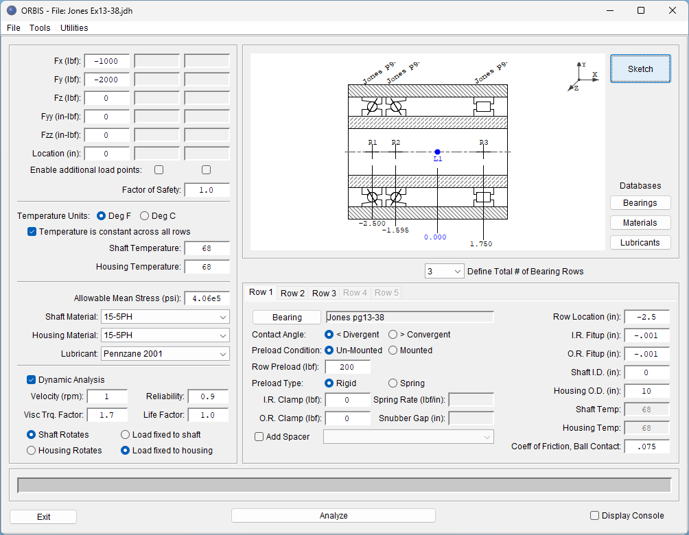
ORBIS is designed with an intuitive interface and a streamlined workflow, making it easy to learn and use. With clear, structured data input and an organized interface, users can quickly access essential tools and parameters. Customizable bearing, material, and lubricant databases further enhance workflow by storing frequently used data, reducing repetitive input and saving valuable time.
Since its initial release in 2009, ORBIS has been continuously developed and improved, ensuring lasting reliability. With our lease-based licensing model, all users receive the latest updates and new features without needing to purchase new versions.
Built on the Java® development platform, ORBIS offers robust compatibility across various operating systems and machine architectures, ensuring reliable performance in diverse environments.
Our mission remains clear—establishing ORBIS as the industry standard for rolling-element bearing analysis.
ORBIS is trusted by industry-leading experts across high-precision engineering fields, including bearing manufacturers, missile and defense contractors, and aerospace engineers. Its advanced capabilities assist these experts in mechanical design, failure analysis, and system optimization, ensuring accuracy and reliability in their critical applications.
For more details about our diverse user base, please contact us.
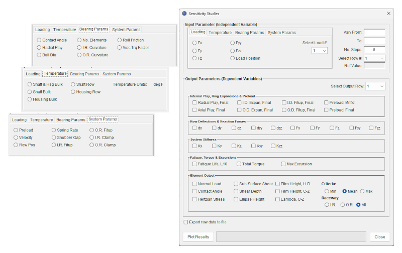
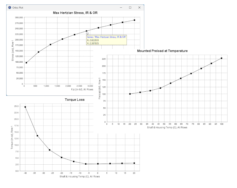
The Sensitivity Studies tool simplifies the analysis of how different input parameters affect bearing system behavior. By plotting selected system variables against independent inputs, users can visualize trends and evaluate performance impact with precision.
The tool accommodates multiple dependent parameters, automatically generating separate plots for each selection. Additionally, users can export raw plot data to a text file for deeper analysis, enabling refined investigations and optimization strategies.
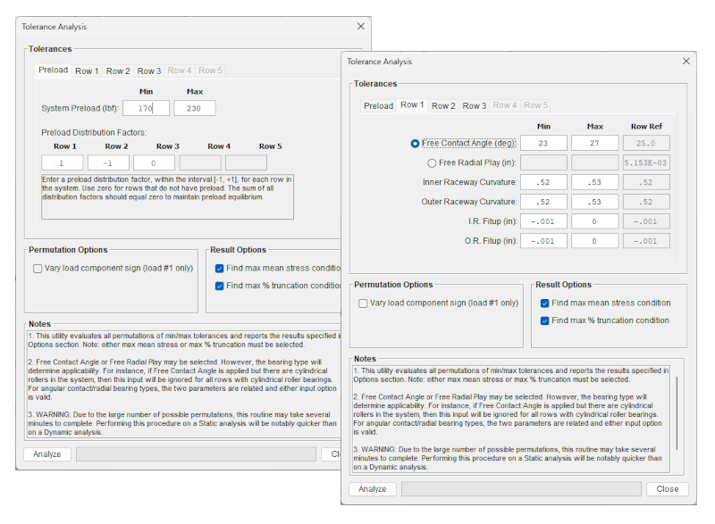
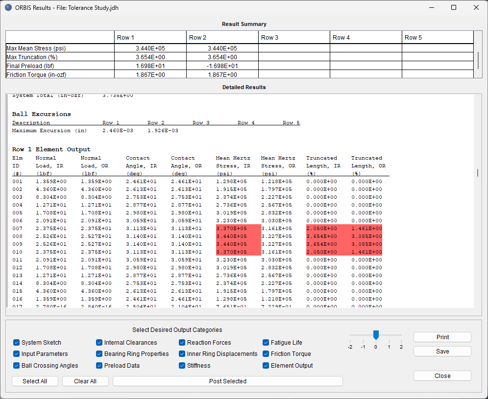
The Tolerance Analysis utility identifies tolerance conditions that maximize contact stress and, if truncated contacts are detected, determines the worst-case set of tolerances leading to the highest percentage of truncation.
The utility systematically evaluates all possible permutations of key tolerances, providing a comprehensive assessment of preload, ID/OD fit-ups, contact angle or radial play, and curvatures. Users define minimum and maximum tolerance values, ensuring a bounding assessment of how variations impact stresses and truncation.
Additionally, the tool allows for sign convention permutations, enabling analysis of all plus-minus load combinations.
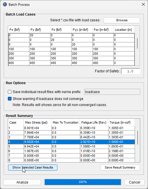
The Batch Process utility imports a .csv file with multiple load cases for rapid evaluation. It automatically processes each case against the configured bearing system and generates a summary of key result parameters such as maximum stress, percent truncation, and resistive torque.
Users can select individual load case results for a detailed stress report. Additionally, the summarized result table can be exported to a text file for further post-processing, while full stress report files for all load cases can be automatically generated and saved for comprehensive documentation.
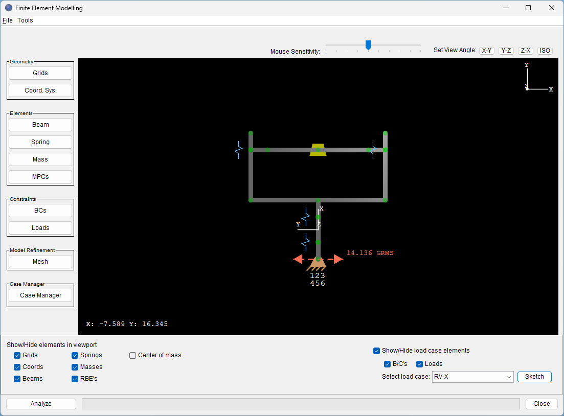
The FEA Load Tool integrates finite element modeling and analysis, allowing users to simulate assembly-level structures surrounding bearings. It applies static and linear dynamic loads, resolving internal bearing reaction forces for further analysis in ORBIS’s non-linear bearing solver.
The tool evaluates static point loads, gravitational forces, and random vibrations, providing a rigorous assessment of bearing loading under real-world conditions.
Check out this video tutorial to see the FEA Load Tool in action.
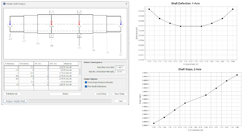
The Flexible Shaft Analyzer accounts for the elastic compliance of the bearing shaft, enabling independent bearing rotation attitudes based on structural stiffness. It utilizes a Timoshenko beam element model, accurately capturing both bending and shear deflections.
Users can define up to 25 unique circular beam elements per shaft, each with customizable cross-section dimensions and material properties. Additionally, the deformed shaft shape can be plotted, providing a visual representation of structural behavior.
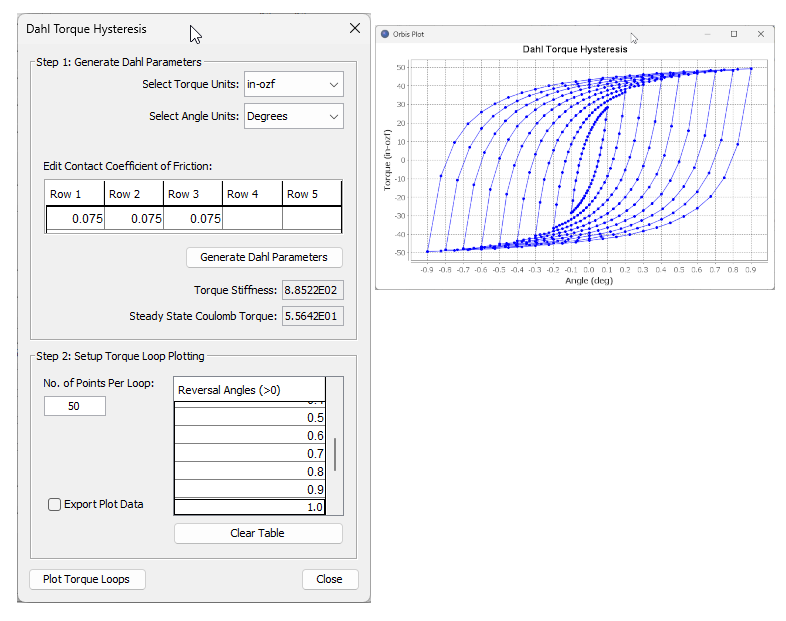
The Dahl Torque Hysteresis utility evaluates the torsional stiffness of the bearing system by analyzing the relationship between torque and angular displacement during startup or direction reversal. This phenomenon occurs within small finite rotation angles, most notably when the direction reverses at speeds low enough to minimize viscous drag effects.
The utility enables quick inspection of the reversing torque slope and steady-state torque, providing engineers with valuable insights into system behavior. Additionally, the tool generates small-angle hysteresis loops for both graphical visualization and data export.
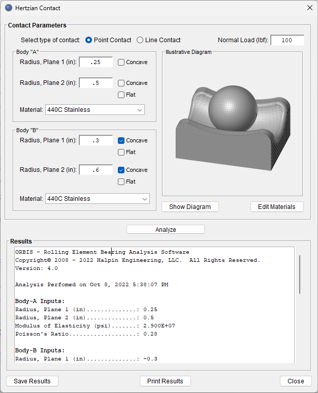
The Hertzian Contact tool makes analyzing classical Hertzian point and line contact problems simple. It solves arbitrary two-body contact scenarios, calculating contact stress, elliptical contact area, linearized contact stiffness, and sub-surface shear stresses.
By leveraging ORBIS’s material database, users only need to specify body radii and normal load, providing a streamlined contact mechanics evaluation.
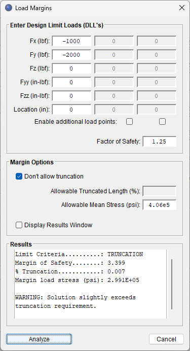
The Load Margin of Safety tool calculates the true load margin for a defined bearing system, determining the percent increase in load that can be applied before reaching a specified limit criterion. Users can select maximum mean stress and/or truncation as the limiting criteria, with the tool reporting the margin at the first identified limit.
Additionally, truncation limits are fully adjustable, allowing users to tailor their analysis by defining a maximum allowable truncation percentage. For example, the user could run a tailored analysis that allows 10% truncation.
Most ORBIS tools support interactive data plotting and data exporting. Plot windows feature click-and-drag zooming, full plot customization, and the ability to save final plots as image files for documentation.
For seamless integration with other software, data exporting provides delimited text file formats, providing easy import into applications like Microsoft Excel® or Matlab®.
ORBIS requires the following minimum system requirements: